Design Process
Purpose
This set of landing gear was designed for NYU Rogue Aerospace’s 2025 NASA University Student Launch Initiative (USLI) vehicle. The payload mission for competition was to collect and transmit a packet of data collected during flight to a NASA receiver. Placing the transmitting antenna above the ground by about 1.5’ ensured proper transmission of the data packet even in the presence of ground foliage. With the landing gear extended and the transmitting antenna at the top of the payload, the antenna would be placed at around this height–giving the signal the clearance it needs to transmit without any problems.
Design Goals
- Deploy landing gear between 5 seconds after main parachute deployment and before touchdown–roughly 40 seconds.
- Deploy reliably under the descent conditions.
- Fit within the payload module while allowing space for the radio electronics and flight computer.
Initial Design
During the initial design of the landing gear I took inspiration from camera tripod legs as they are designed to extend into a large and stable base while collapsing into a slim and portable shape. Where a camera tripod relies on someone to push out the legs, the landing gear in the payload module required a robust system to push out the legs.
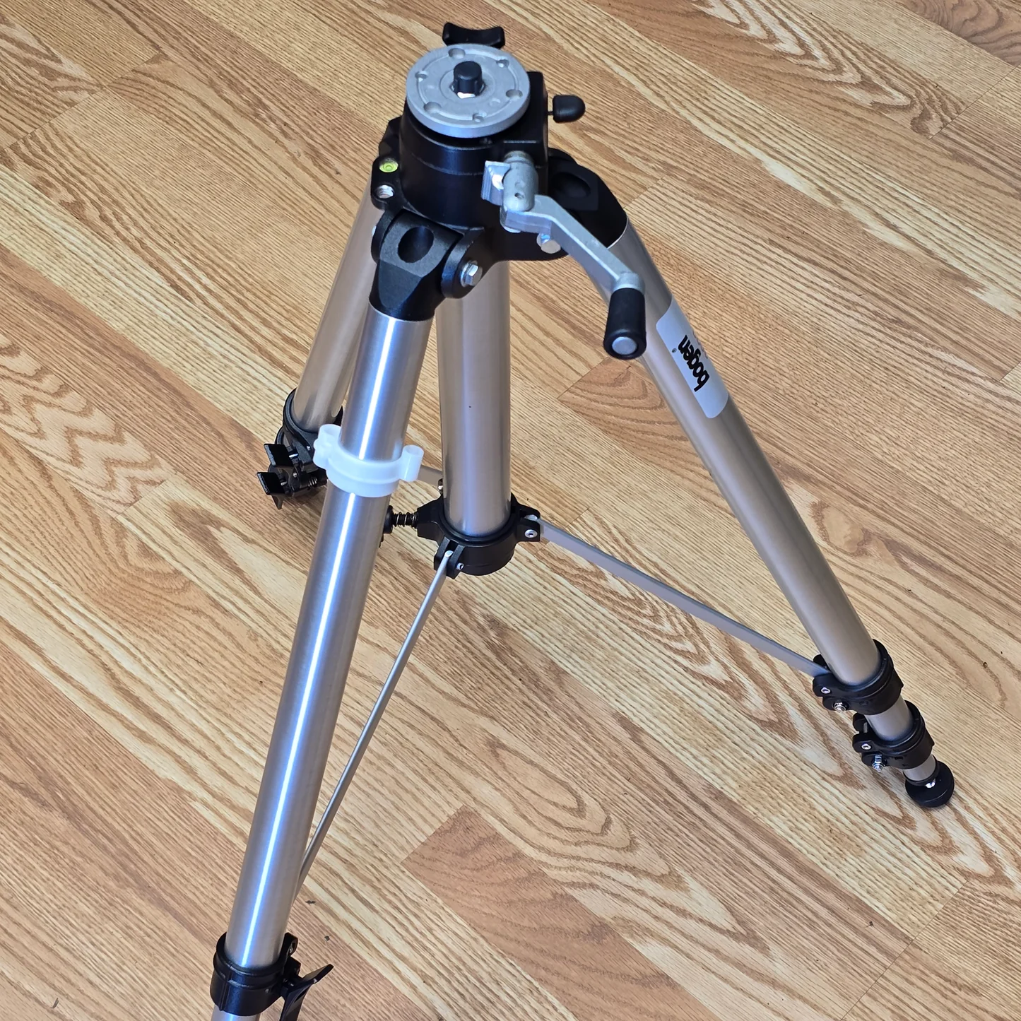
Tripod inspiration example.
This system for legs deployment took a few design iterations to get right. My first thought was to place a compression spring on the middle shaft of the landing gear which would push out the legs when current ran through a nichrome wire which held the legs during ascent. While this would push out the legs in a very short period of time, the possibility of the nichrome wire breaking or coming loose during ascent would be catastrophic to the aerodynamic stability of the rocket. So this design would fit design goal 1 pretty well but have the potential to fail design goal 2 catastrophically. Additionally, any compression spring long enough to apply a force when the legs were deployed would be applying a very high force when in its launch position.
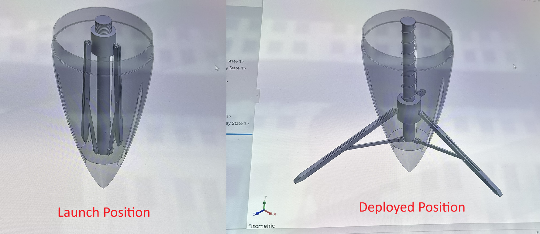
Initial landing gear design using a compression spring.
The lead screw method solves this reliability problem by only deploying when it’s triggered by the flight computer. This means we have much more control over this premature deploying failure event. A stepper motor was chosen to spin the threaded rod. Early on, I failed to run a calculation on the torque of the stepper motor compared to the estimated torque required to deploy the gear. The result was a very underpowered stepper motor.
Prototype
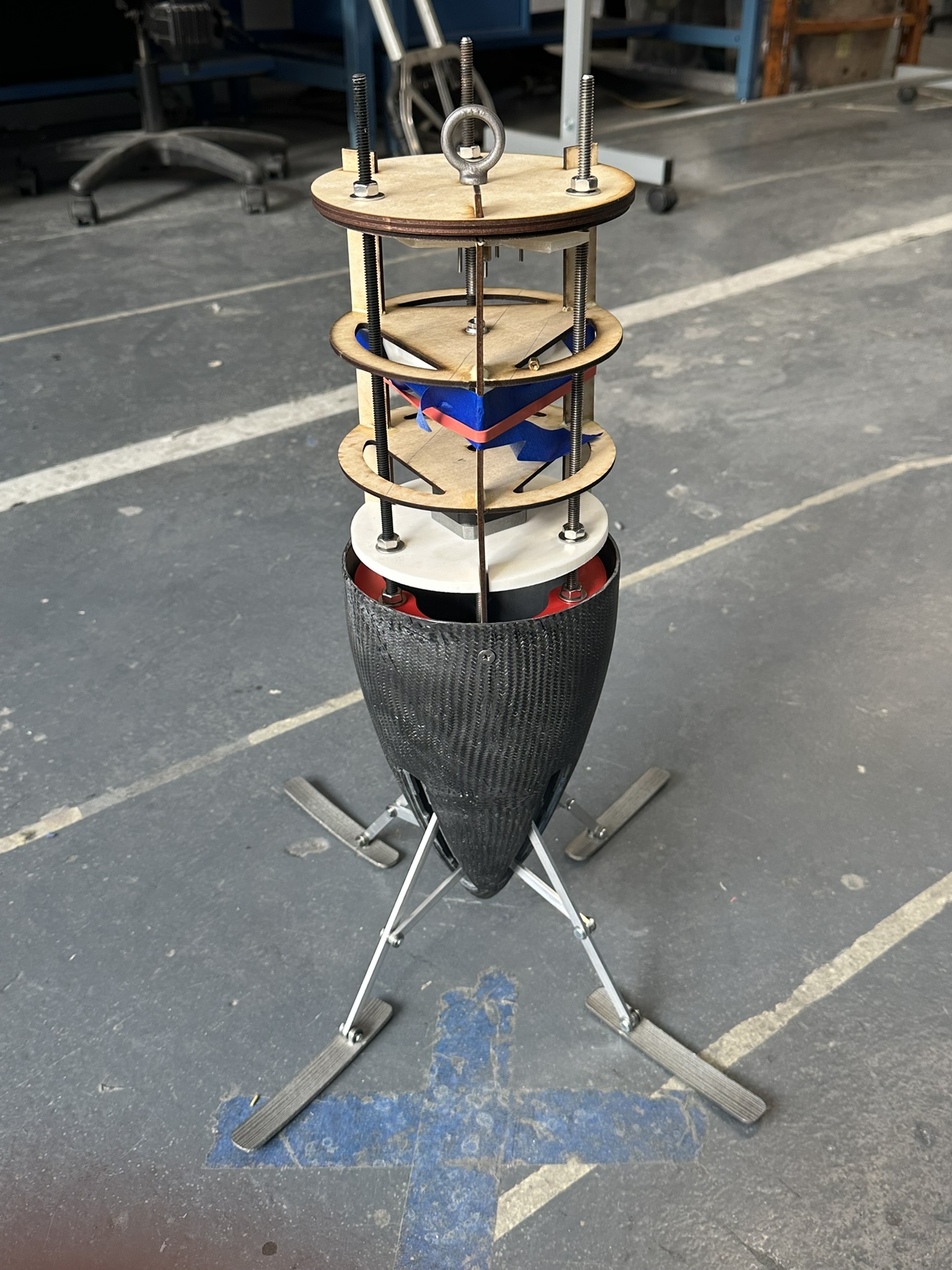
With the SolidWorks assembly updated to the stepper motor driven lead screw, I had concerns with the assembly of the system. There were lots of small parts in the design–small clevis pins, thin aluminum rods, and a small bearing imbedded in the tip of the nose cone. At this point in the semester, the club was rebuilding the launch vehicle following a recovery failure. This meant pretty much all the remaining budget was going to this vehicle rebuild and I had no money to work with. I decided to create a prototype that would cost nothing while putting to rest my assembly and stepper motor torque concerns. I ended up with a laser cut design which used only 1/8” birch which was lying around, wood glue, and parts which were already manufactured. The design was such that it could be disassembled and all the already manufacture parts could be taken off and reused for the final assembly.
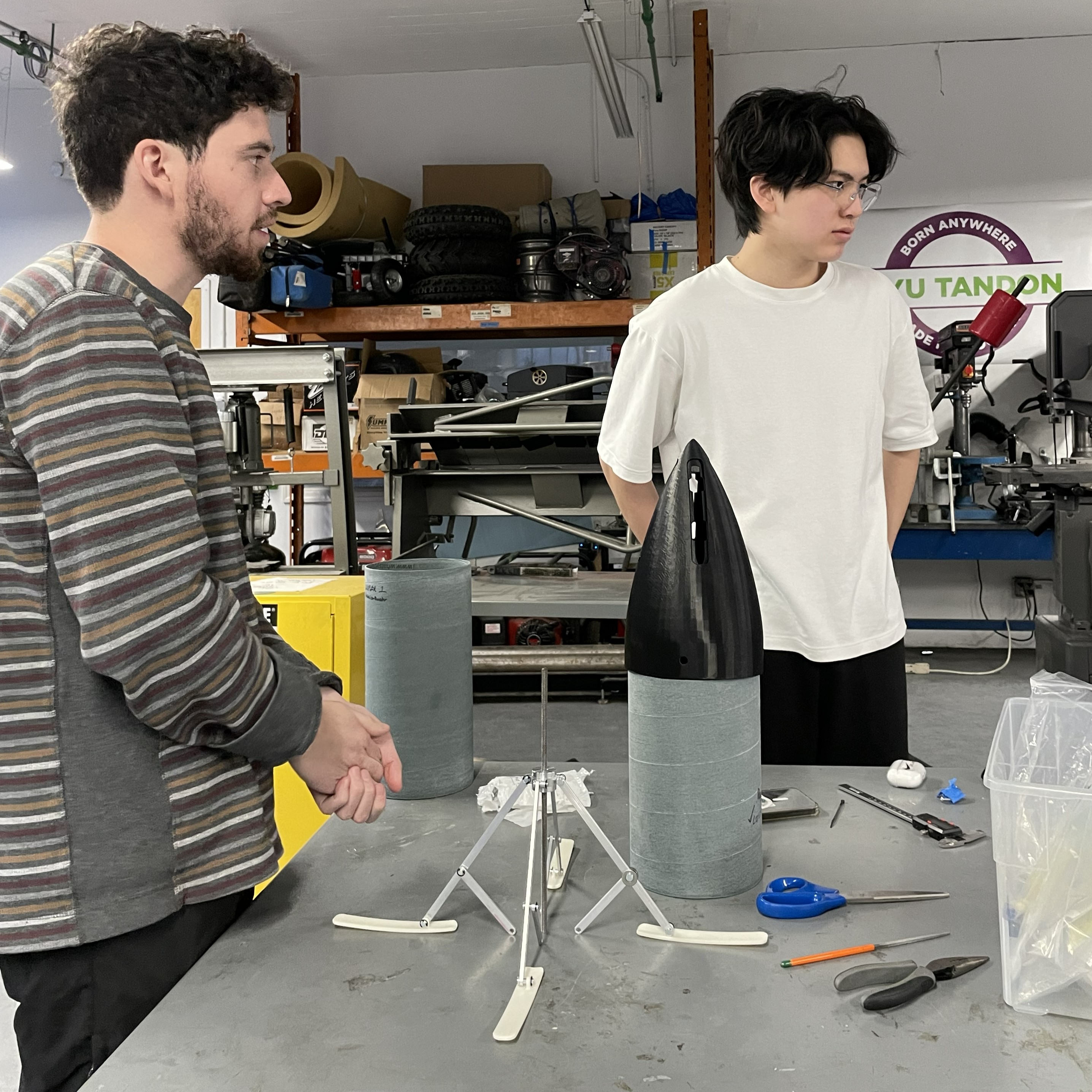
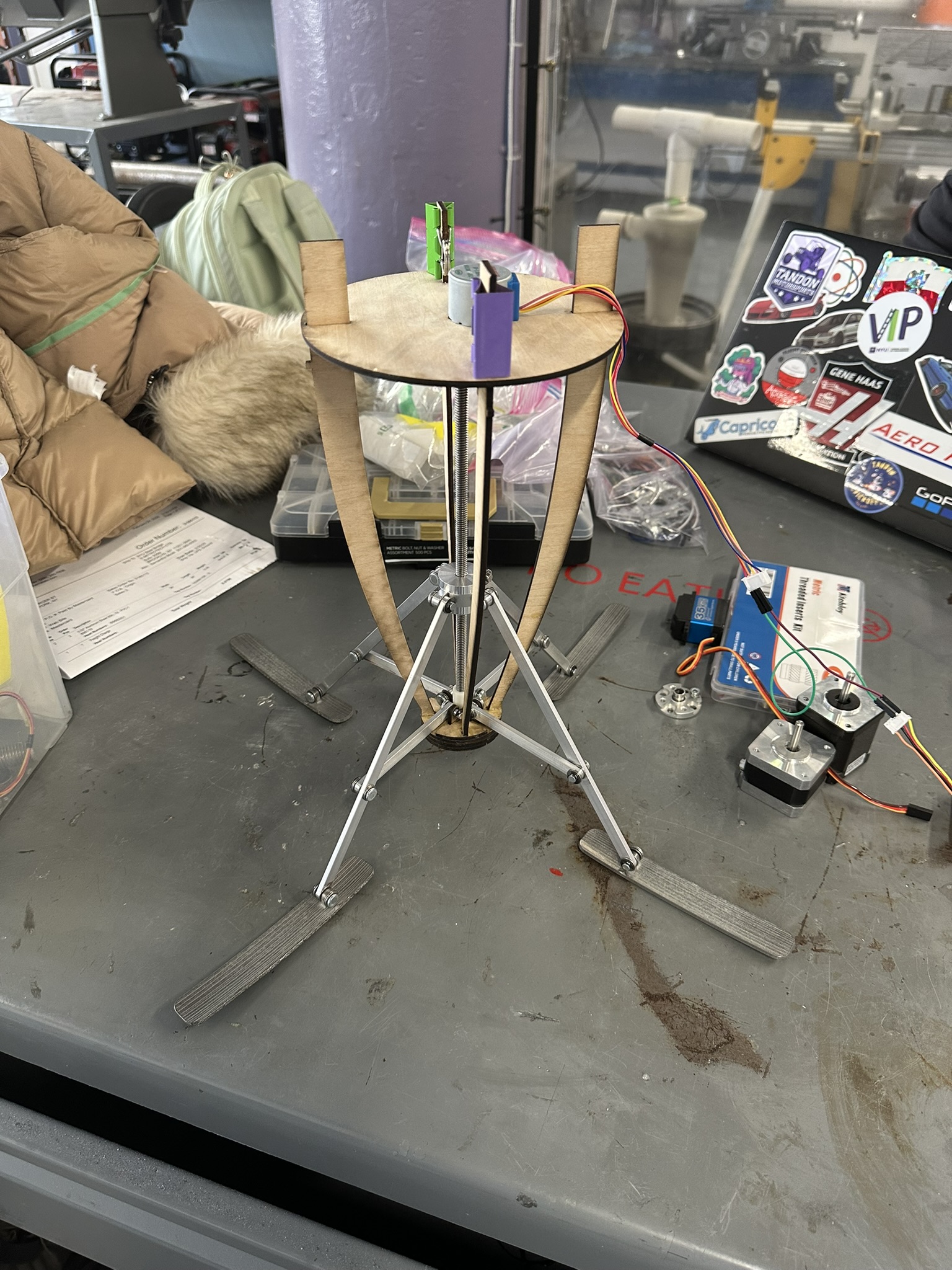
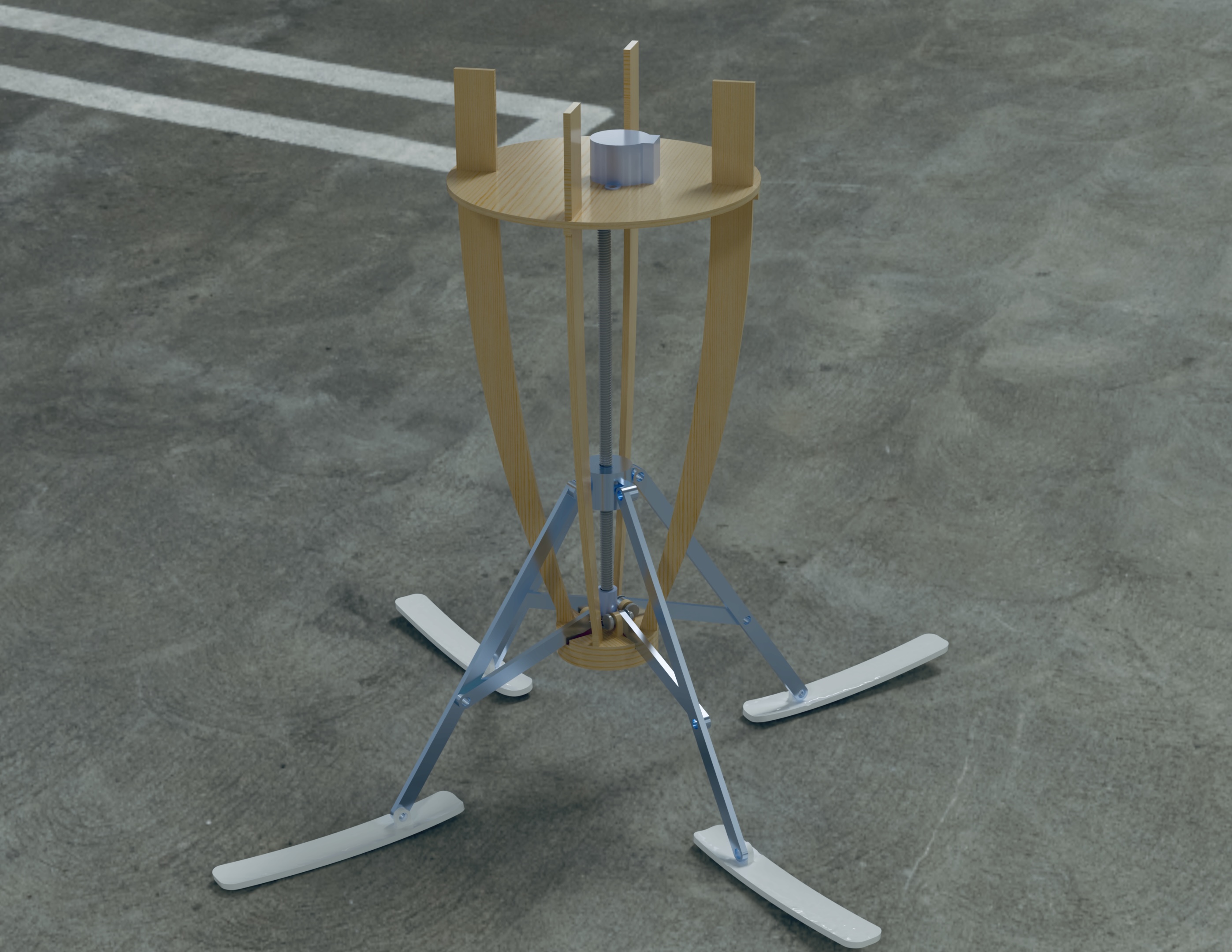
Landing gear assembly (left), wooden prototype, and render from SolidWorks Visualize (right).
Following the testing of this prototype, I learned two things:
- Assembly of the system is possible and not too difficult. However, inside the tight space of the nose cone it may be slightly more difficult.
- The stepper motor is incredibly underpowered. Both the stepper motor and the power source need to be changed.
I went back to the drawing board and selected the NEMA 17 for its increased maximum torque and reliability.
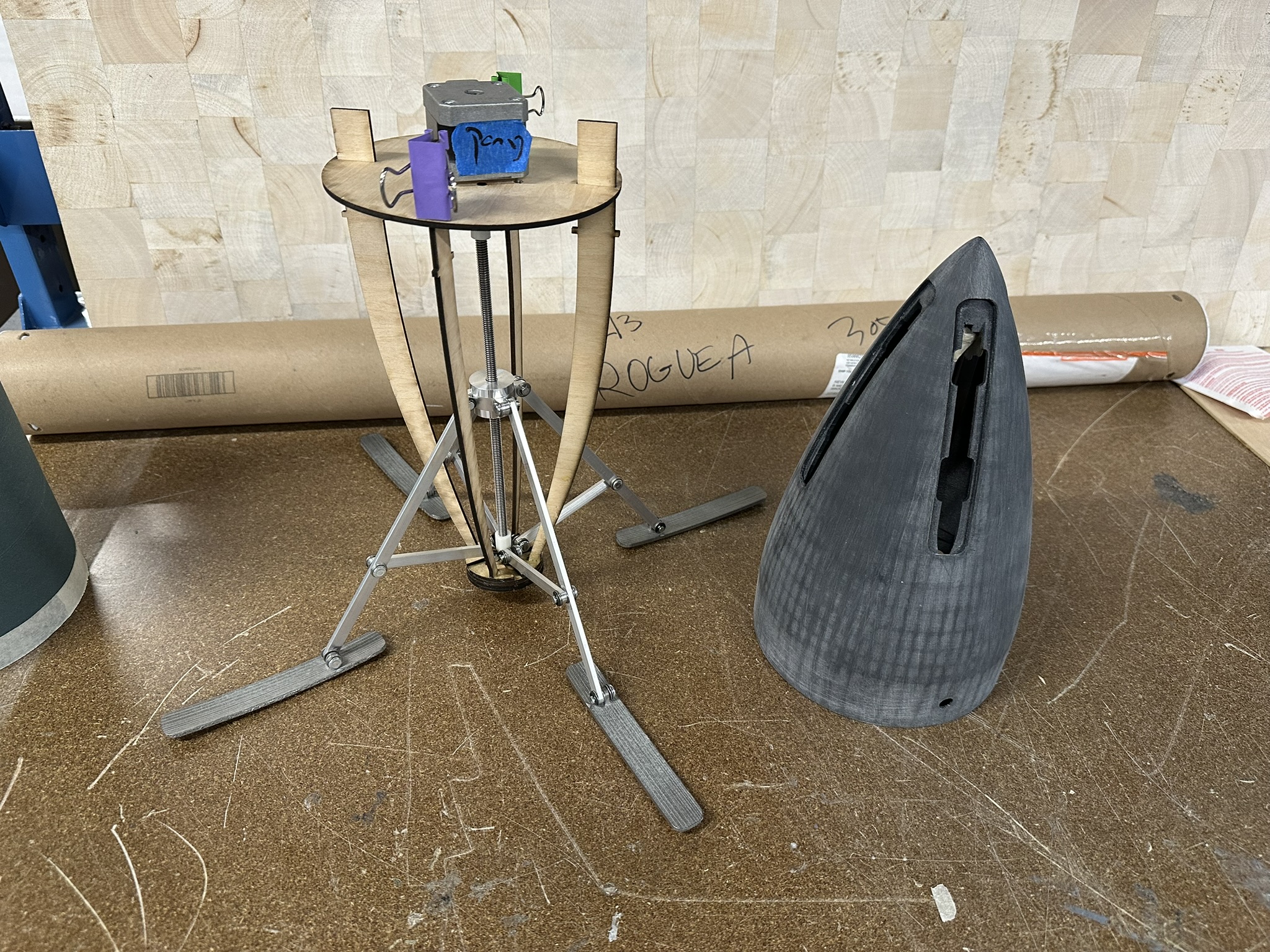
Wooden prototype and nose cone 2 print.
Landing gear prototype with NEMA 17 stepper motor test.
Nose Cone Manufacturing
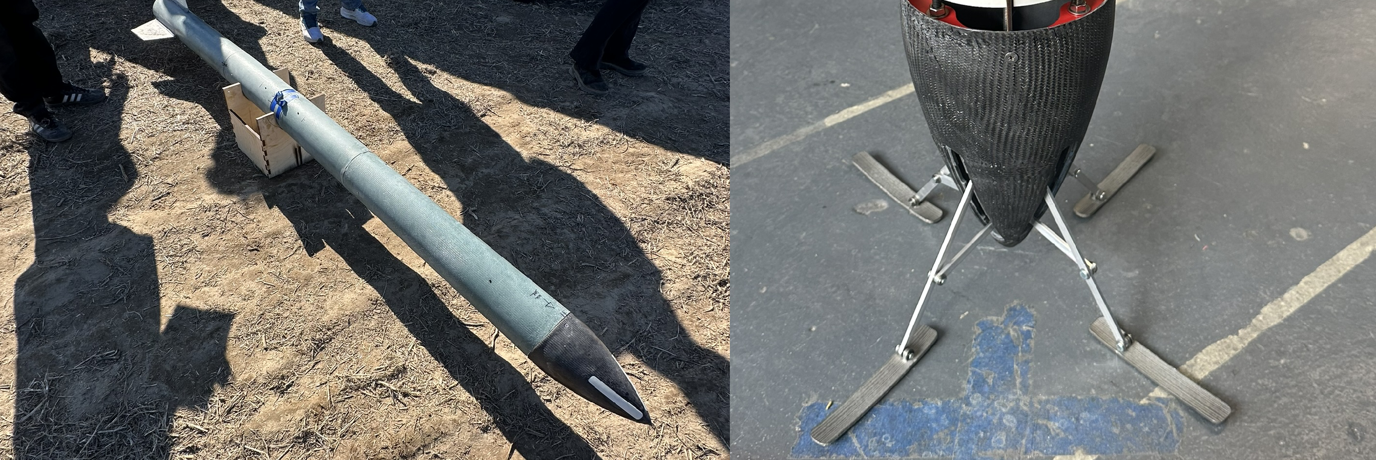
While I was the responsible engineer in charge of the landing gear, I also helped out with the nose cone fabrication as this was a part of my assembly. The nose cone was 3D printed out of ABS-CF10 on a Stratasys F370. In order to additionally strengthen the print, one layer of carbon fiber was overlaid over the exterior of the nose cone. The process of applying this layer of carbon fiber was complicated by the geometry of the nose cone, a von Kármán profile which is relatively slim compared to other profiles, and the slots required for the legs to extend from the inside of the nose cone.
Nose Cone 1
The first nose cone made was printed at an angle and had a small piece break off along the print line due to a printing error. This piece was reapplied with steel epoxy. Due to the printing error, the team decided to remake the nose cone but continue with the lay up of this first nose cone to test the layup process.
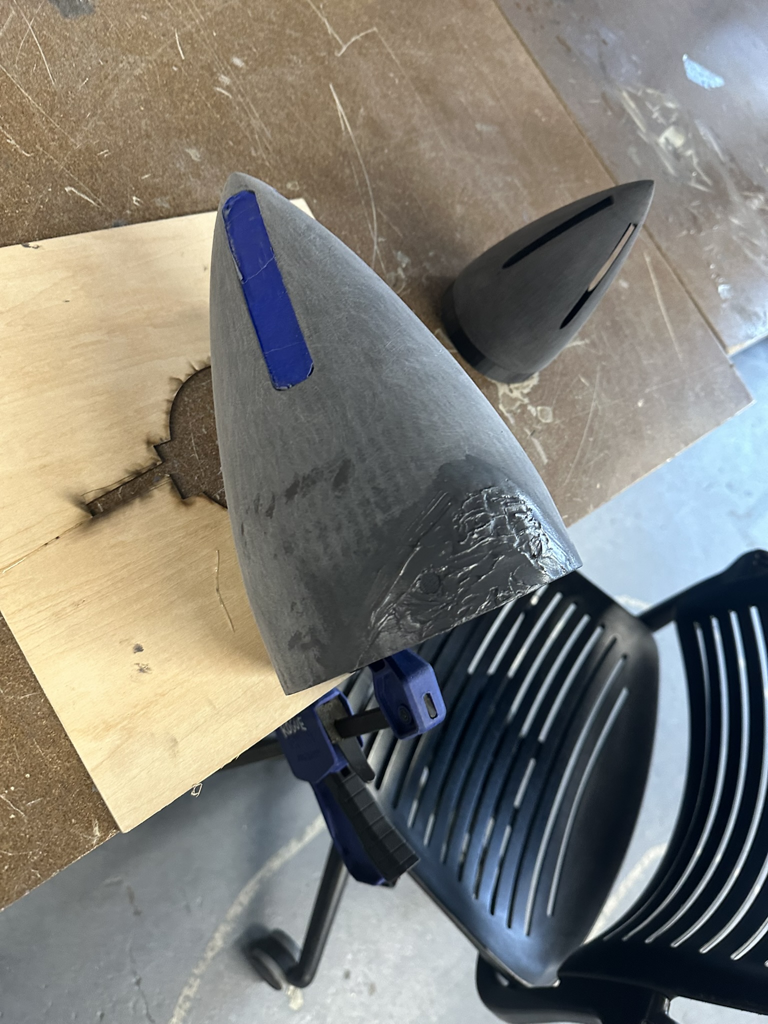
Nose cone 1 print after steel epoxy repair.
The print was then sanded as preparation for the epoxy bond to the carbon fiber. The layup of the nose cone was done with a carbon fiber biaxial sleeve from Soller Composites. Near the top of the nose cone, the sleeve bunched up quite a bit and made it difficult to get a smooth surface.
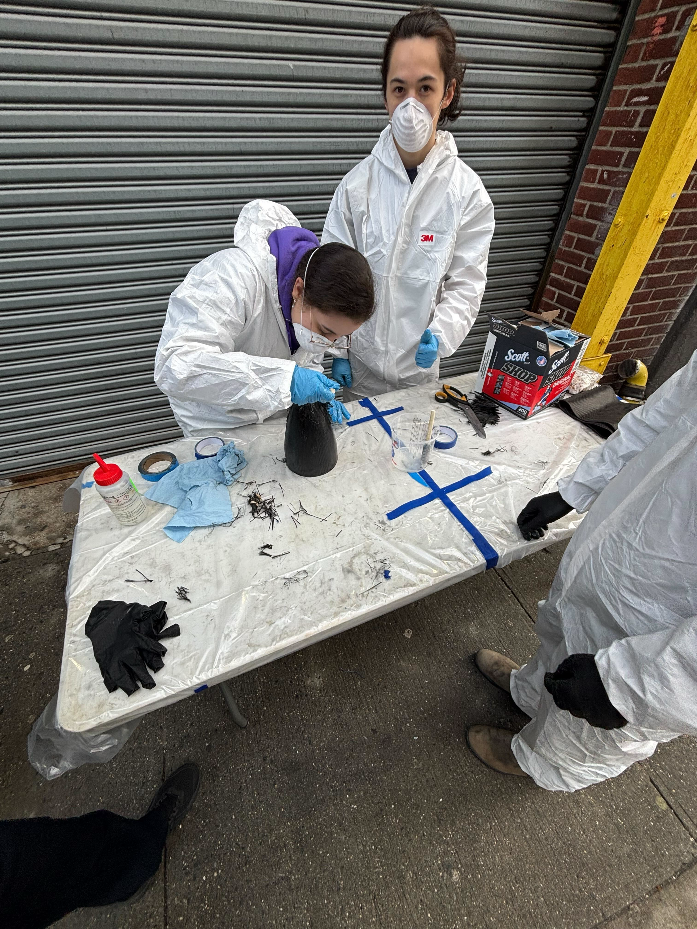
Nose cone 1 during lay up process.
After the lay up and curing, the nose cone exterior was sanded with a Dremel to get a smooth surface and clean up the edges. This process took about a week and proved difficult due to the bunching up at the top of the nose cone. The result was a surface made uneven by patches of exposed 3D print–especially near the tip of the nose cone.
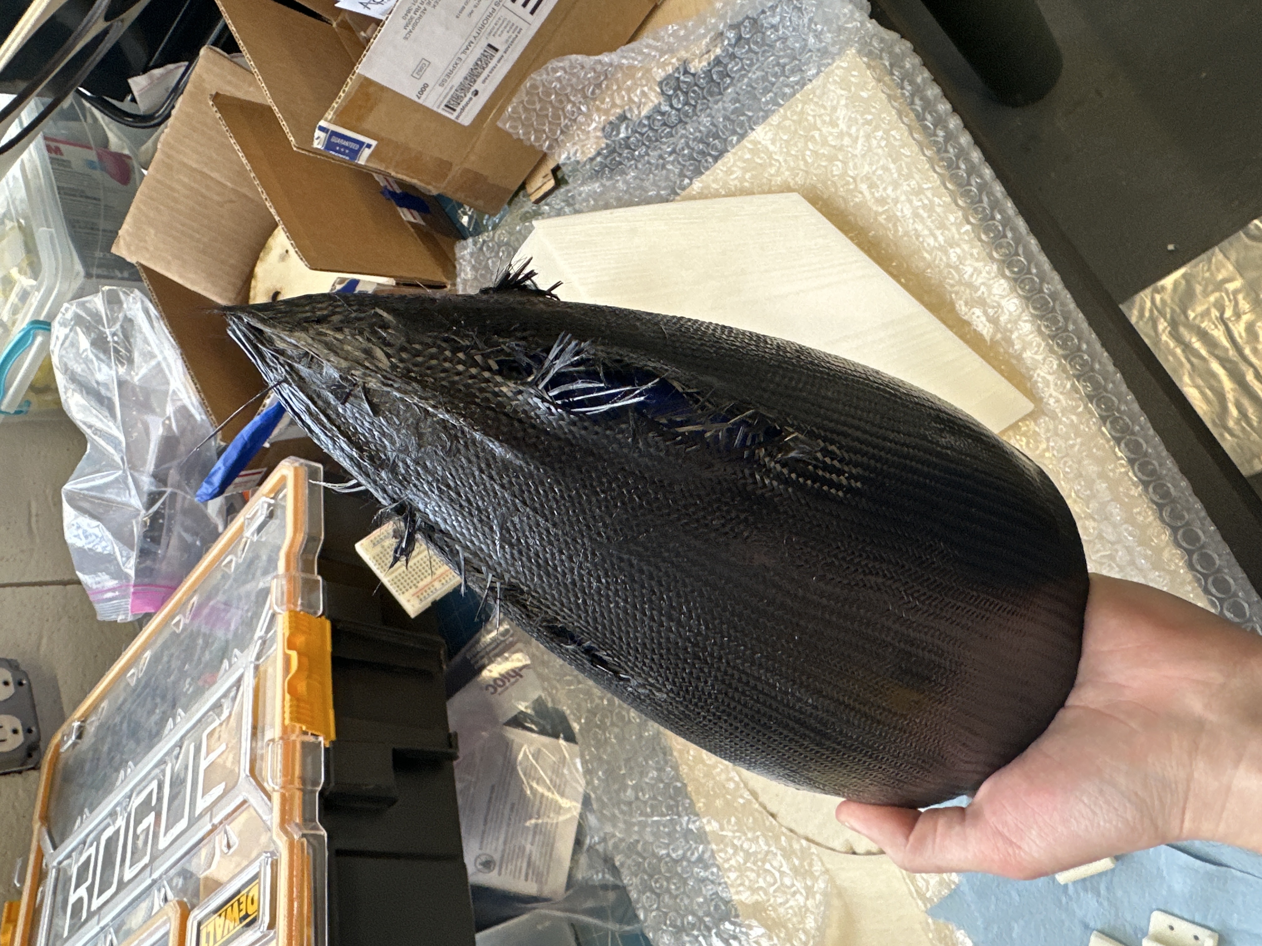
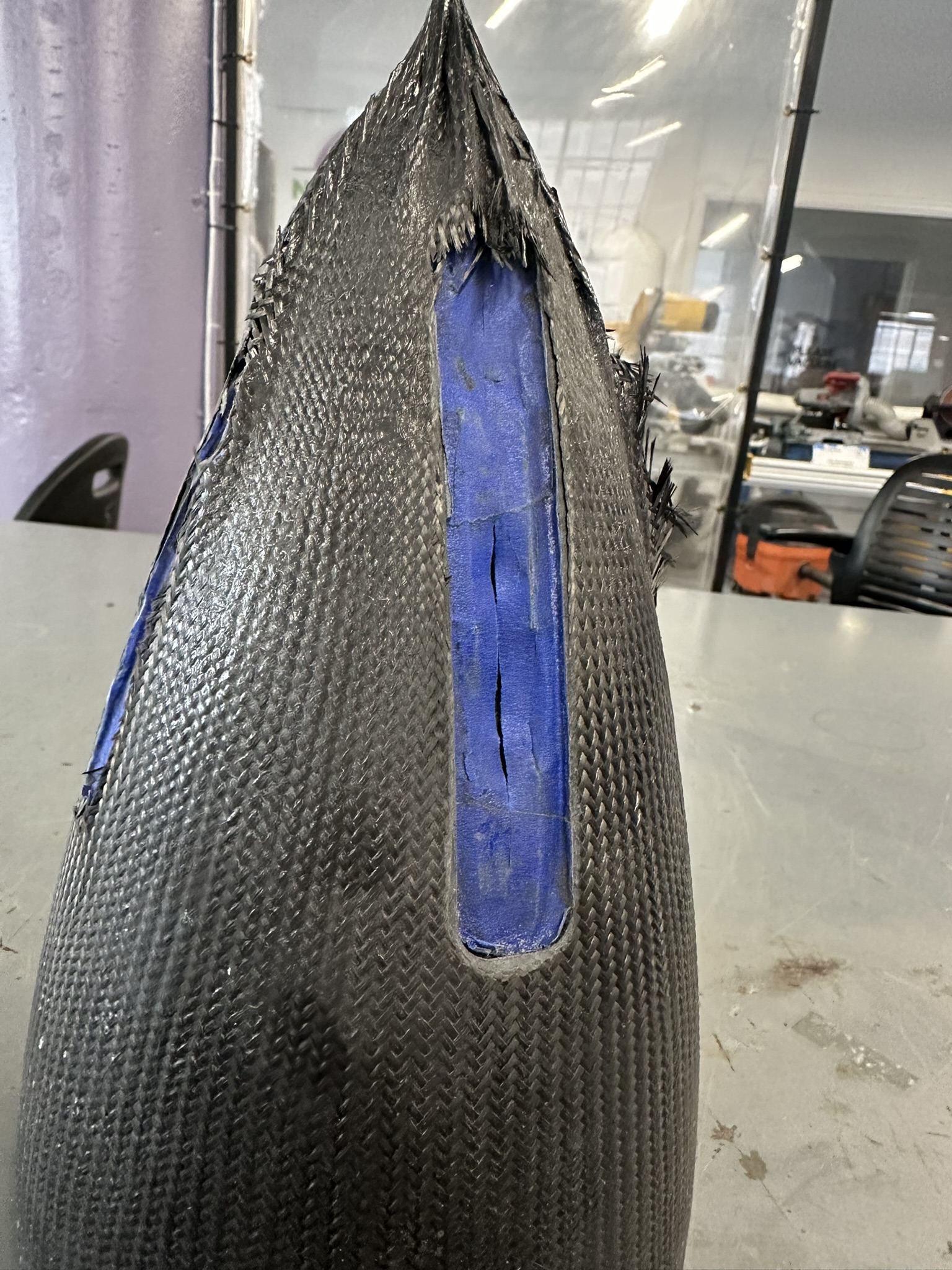
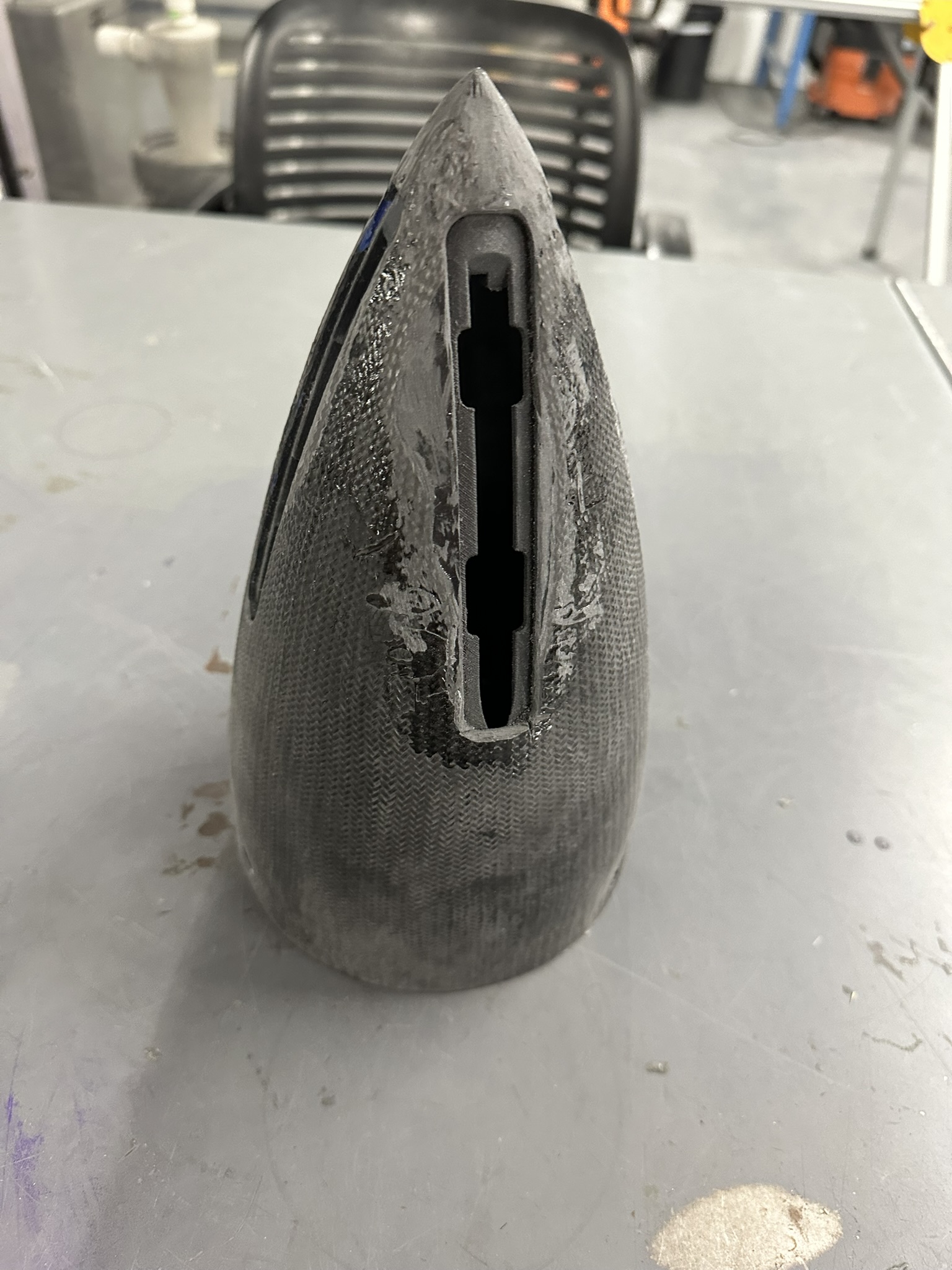
Nose cone 1 directly after lay up (left), during the Dremel operation, and the finished nose cone (right).
This nose cone was flown for the team’s vehicle flight demonstration.
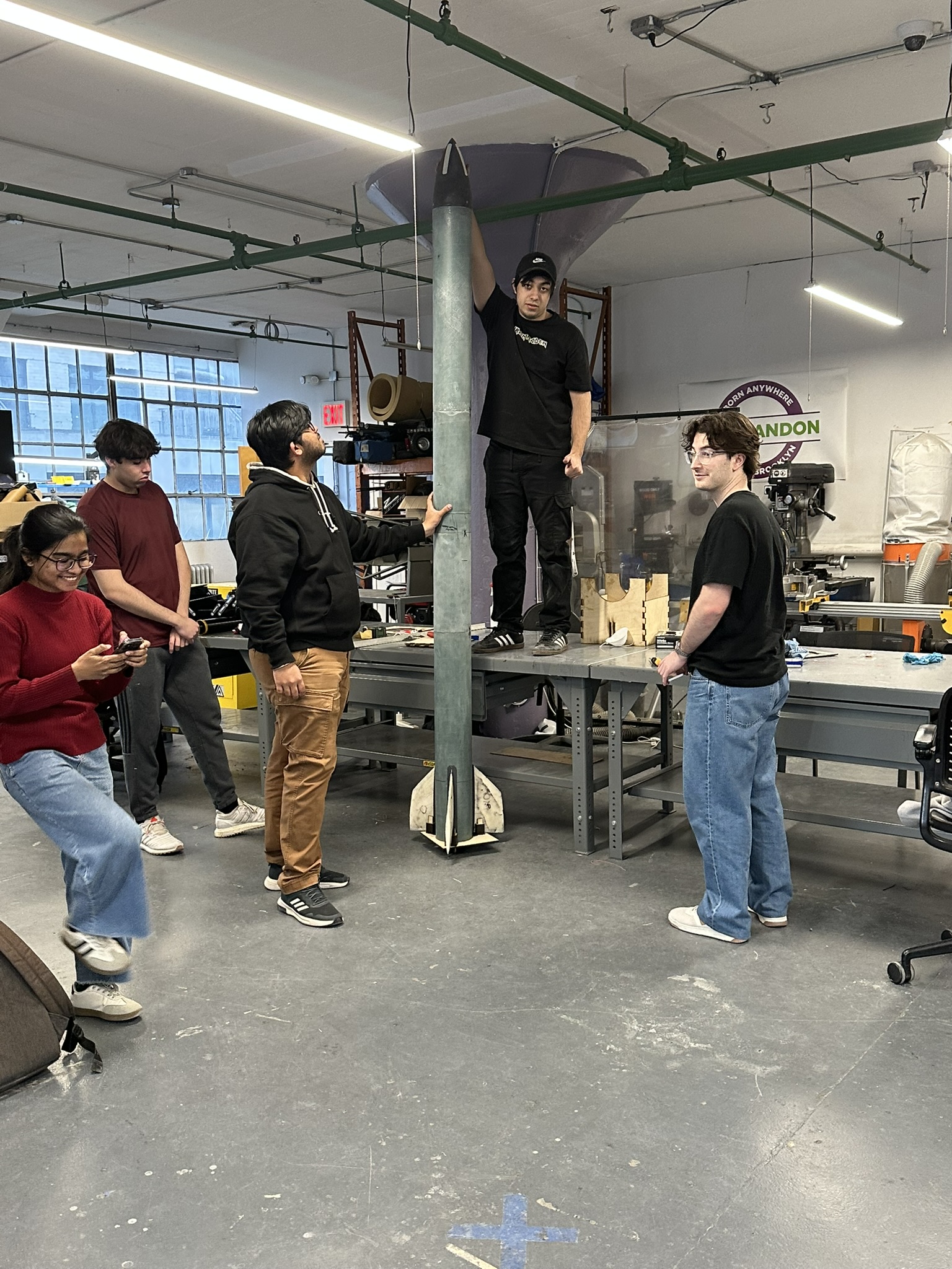
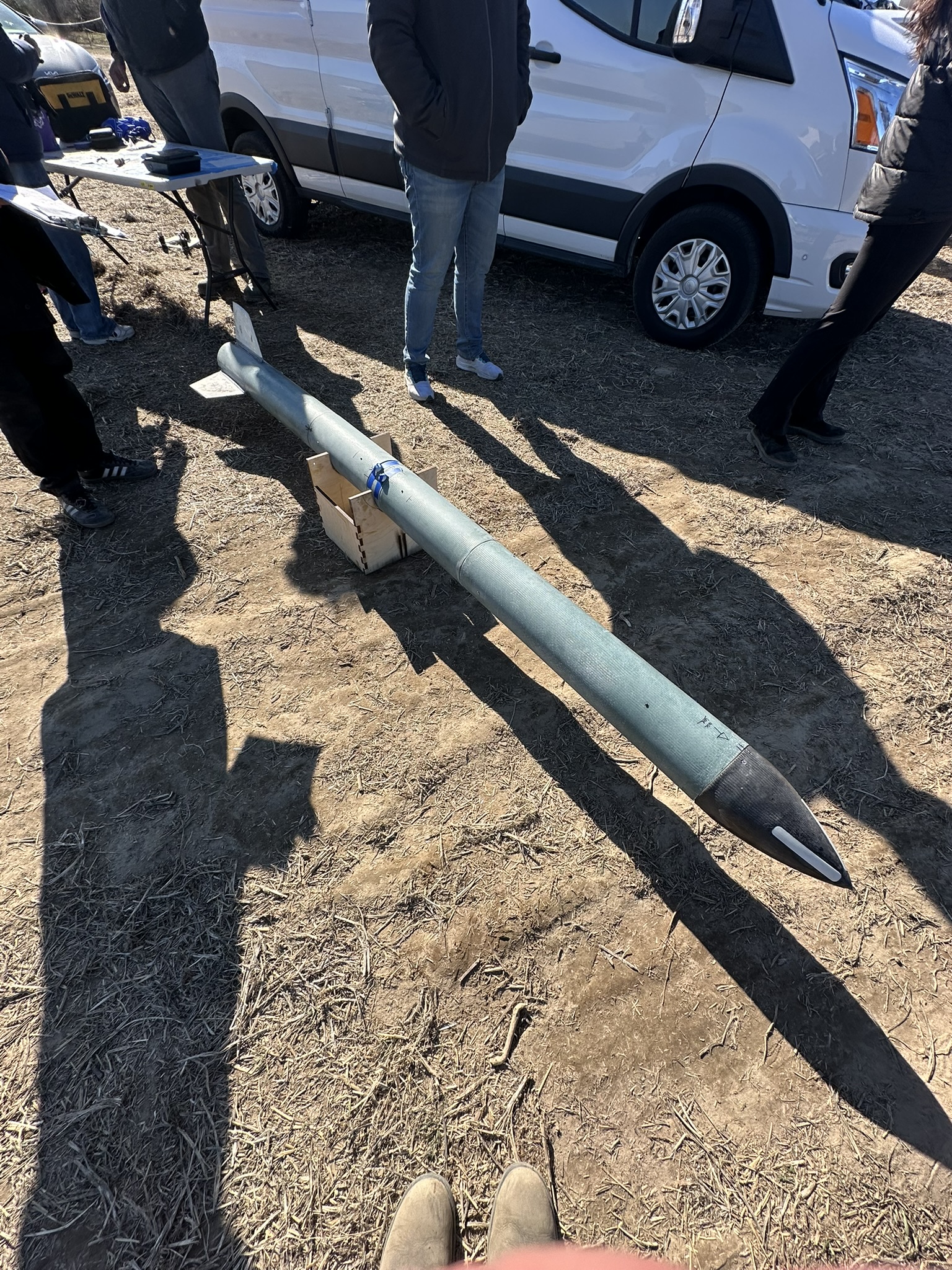
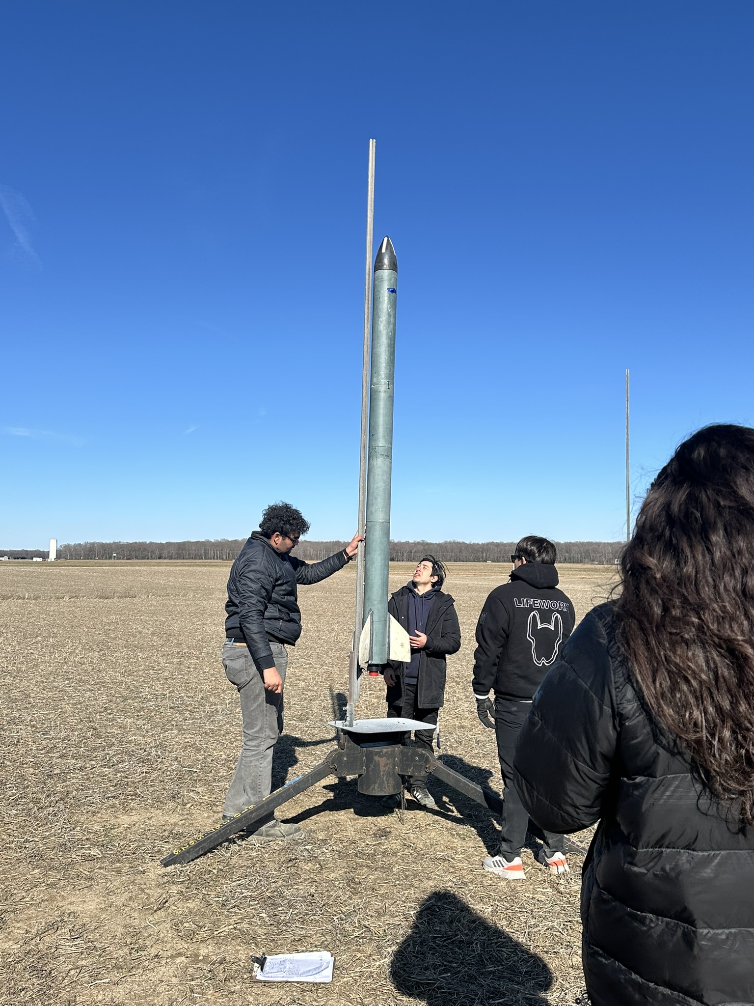
Vehicle demonstration flight.
Nose Cone 2
The second nose cone was printed upright such that the printing lines would be parallel to the radial direction. This reduced the chance of the printing error during the print of the first nose cone. During the over lay process of this nose cone, the same carbon fiber biaxial sleeve was used for the bottom portion of the geometry while a smaller diameter sleeve was used for the top of the nose cone. This reduced the bunching up of the sleeve which made the Dremel step simpler and faster. The lay up was also wrapped in plastic to smooth the surface of the carbon fiber.
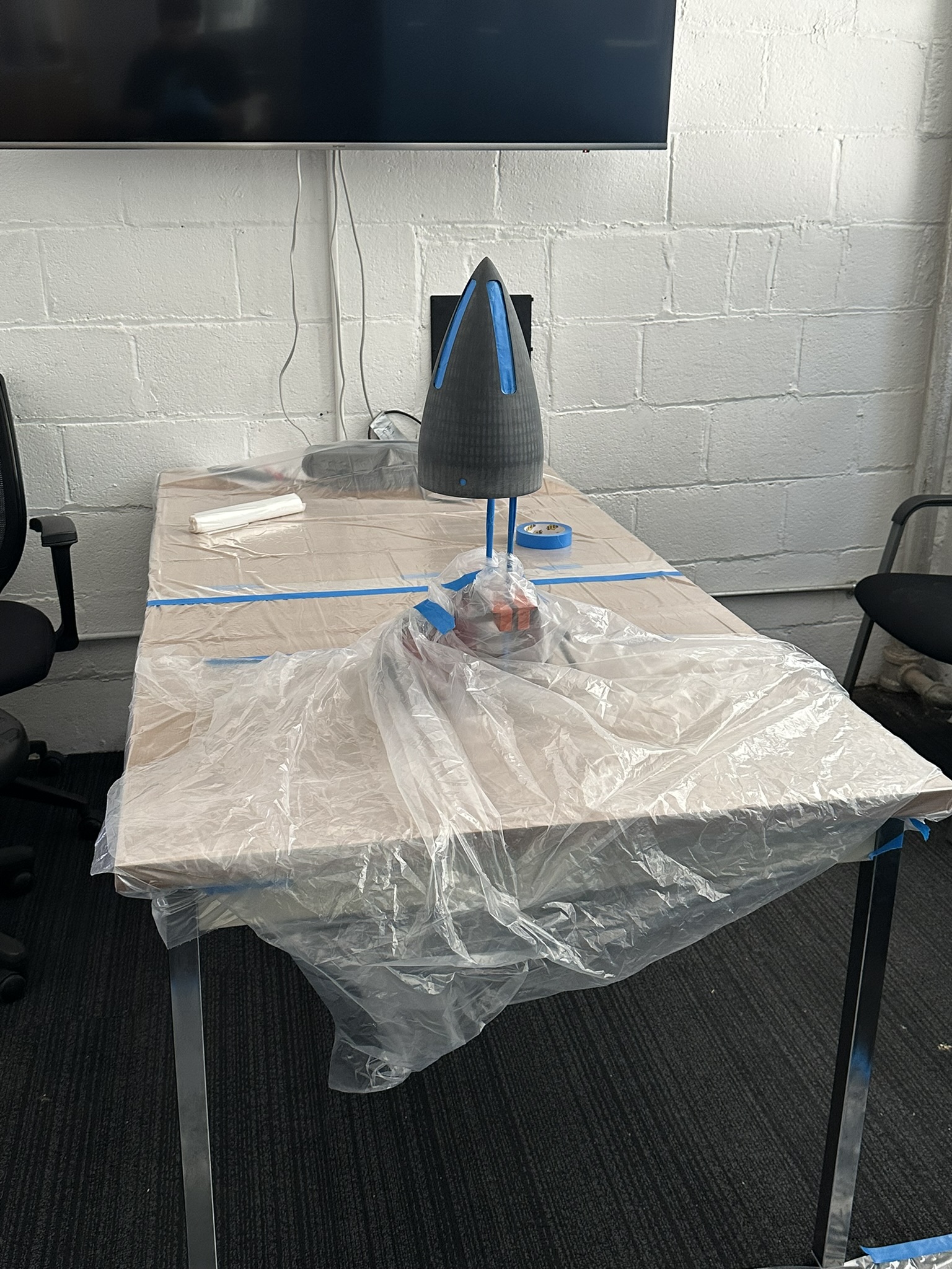

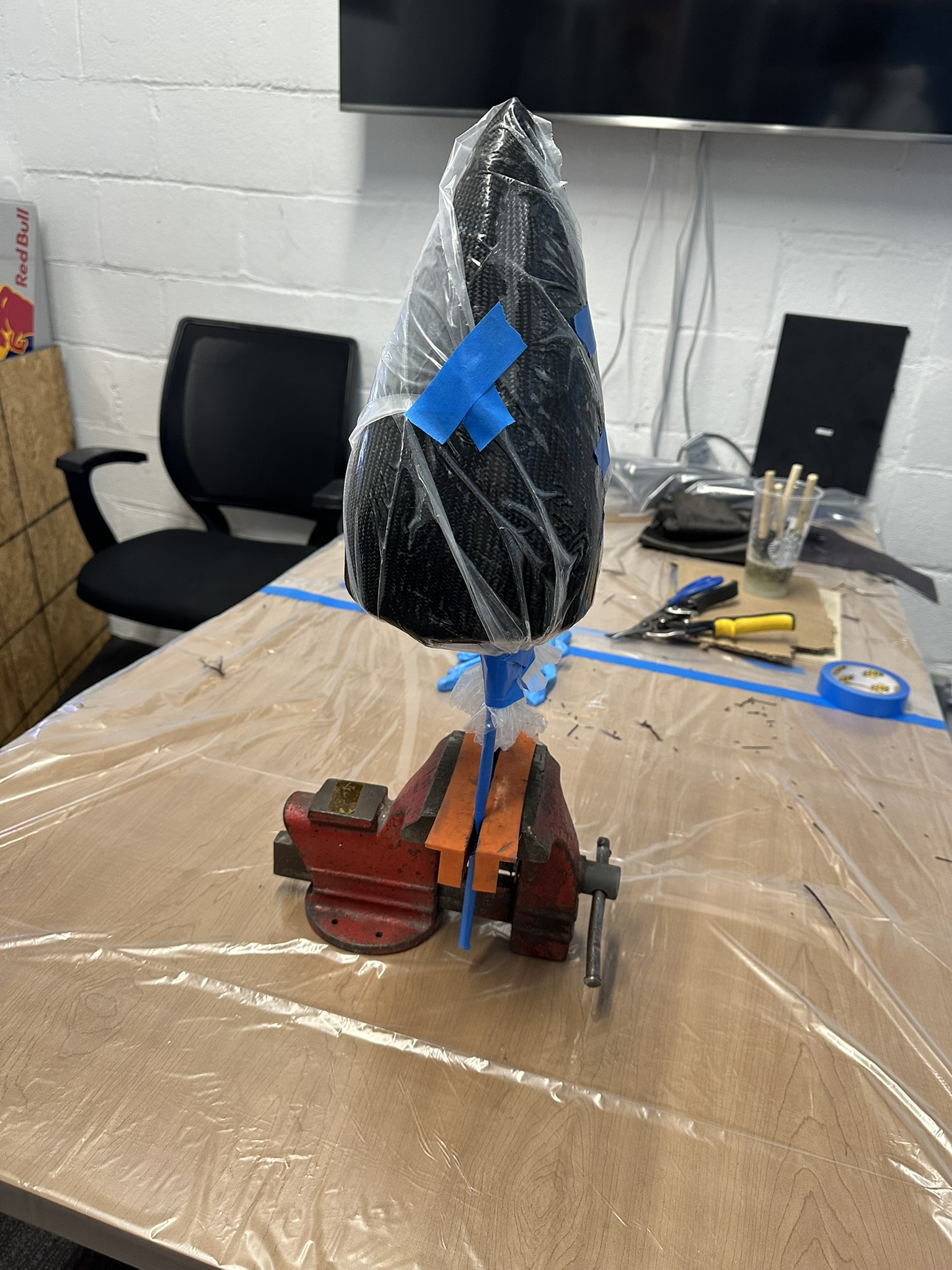
Nose cone 2 during layup.
After the lay up, the nose cone was much smoother than the first try.
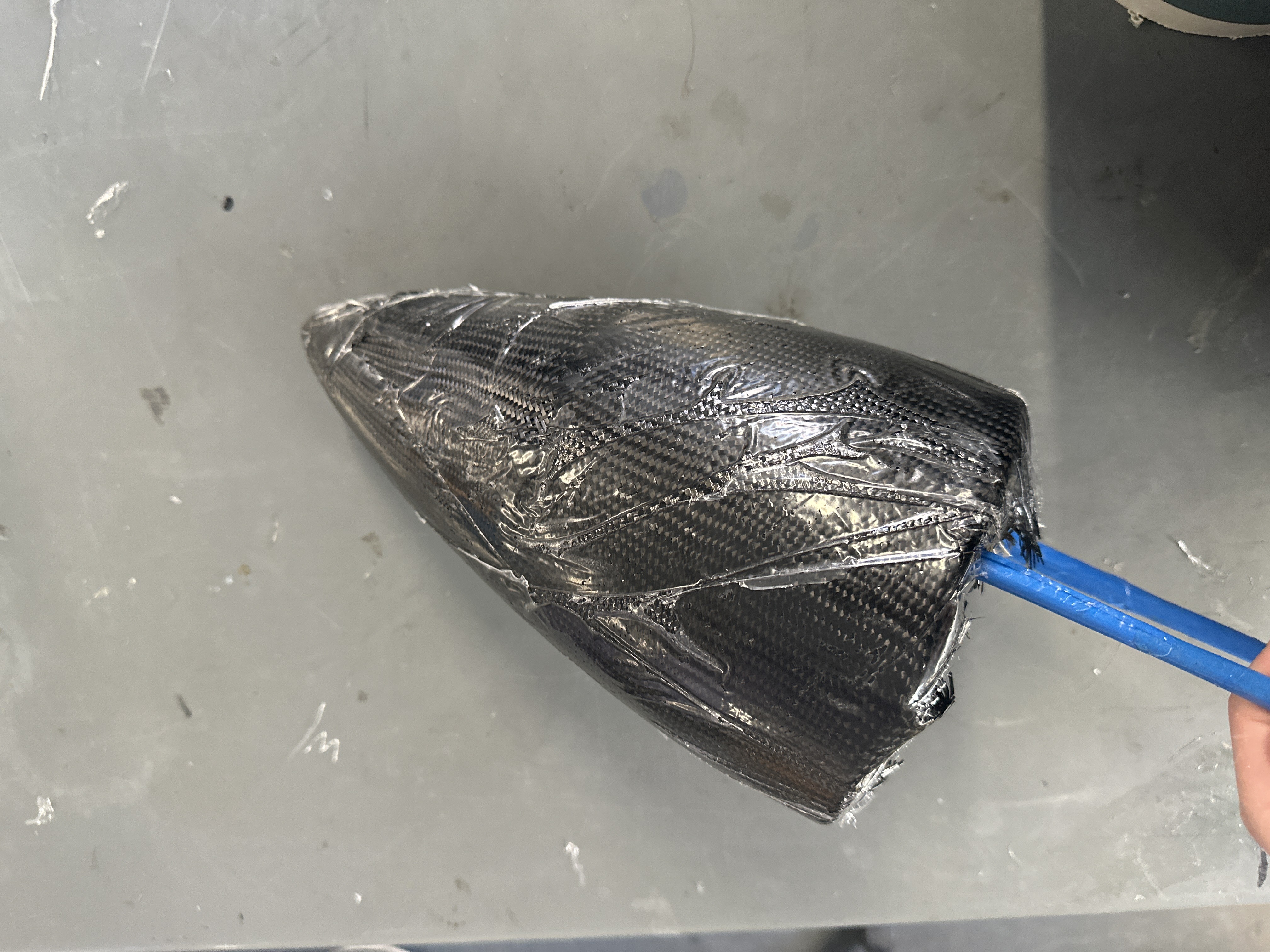
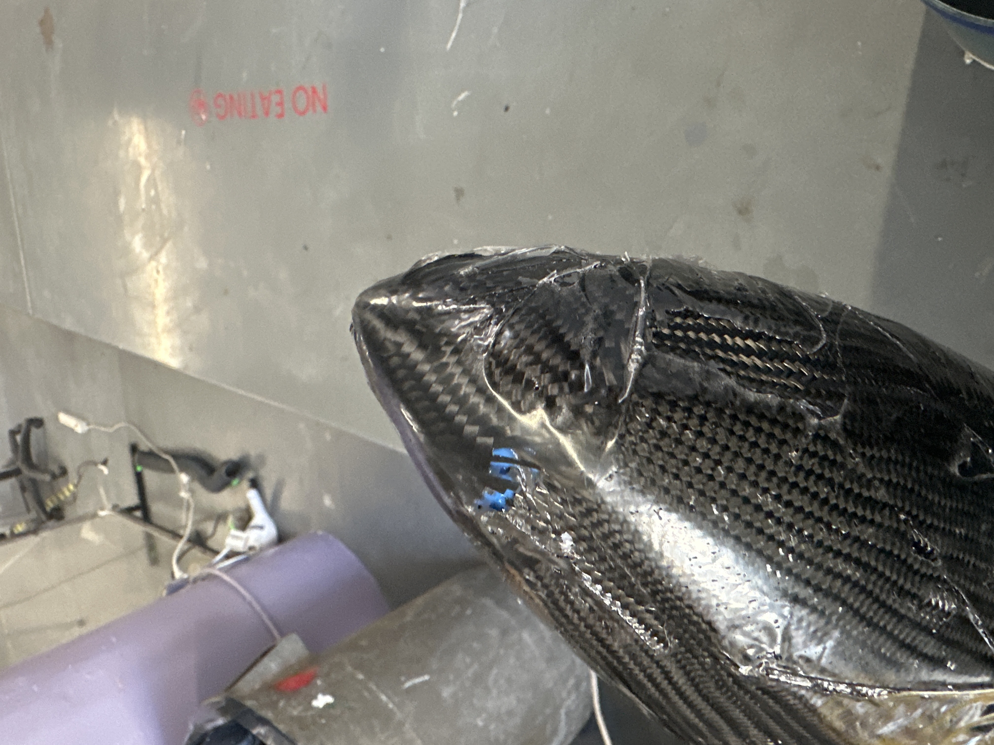
Nose cone 2 after lay up.
By using two different diameters of carbon fiber sleeve and wrapping the lay up in plastic, the Dremel process became much simpler. While it still took about 3 days of work, it was easier and resulted in a much more smooth surface.
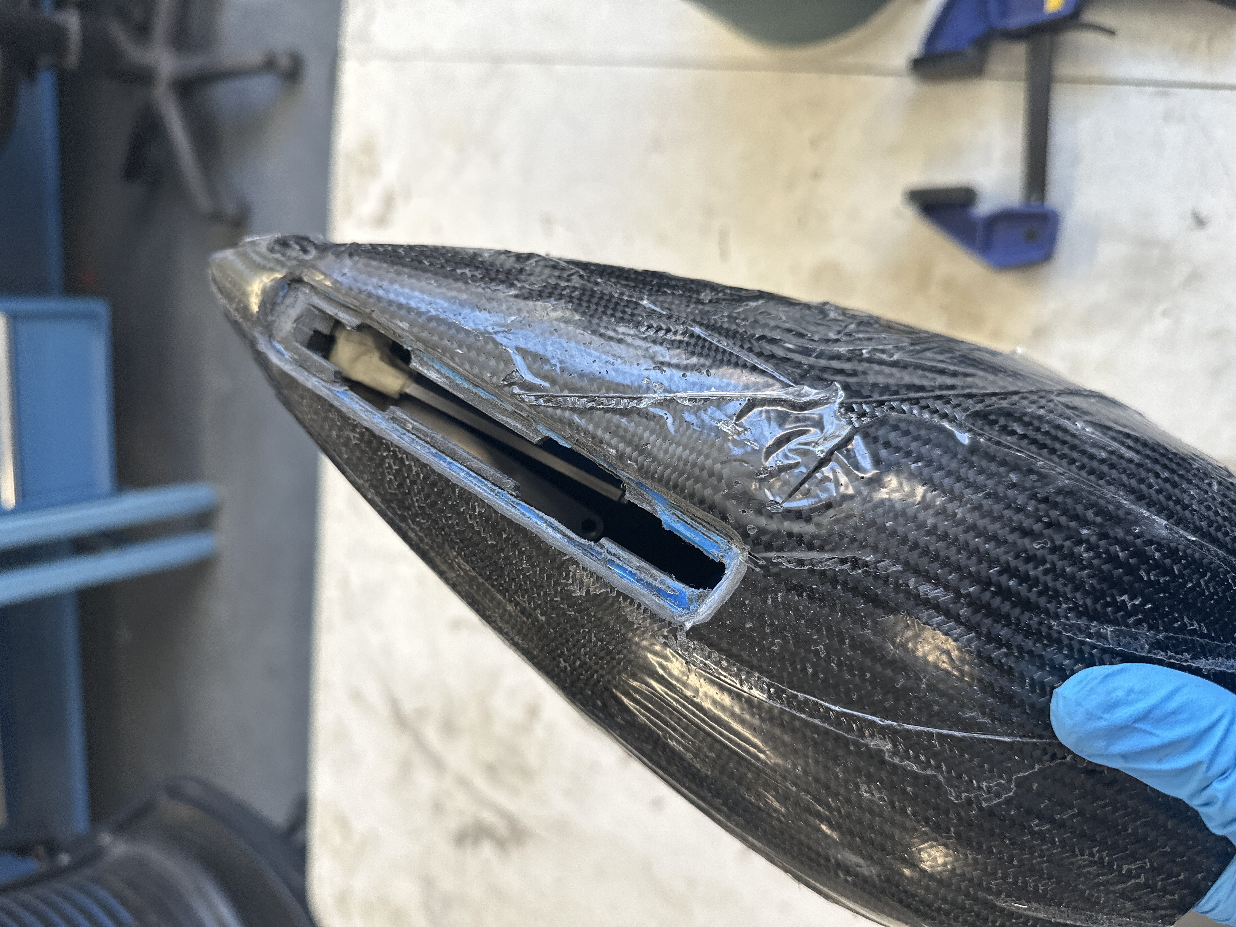
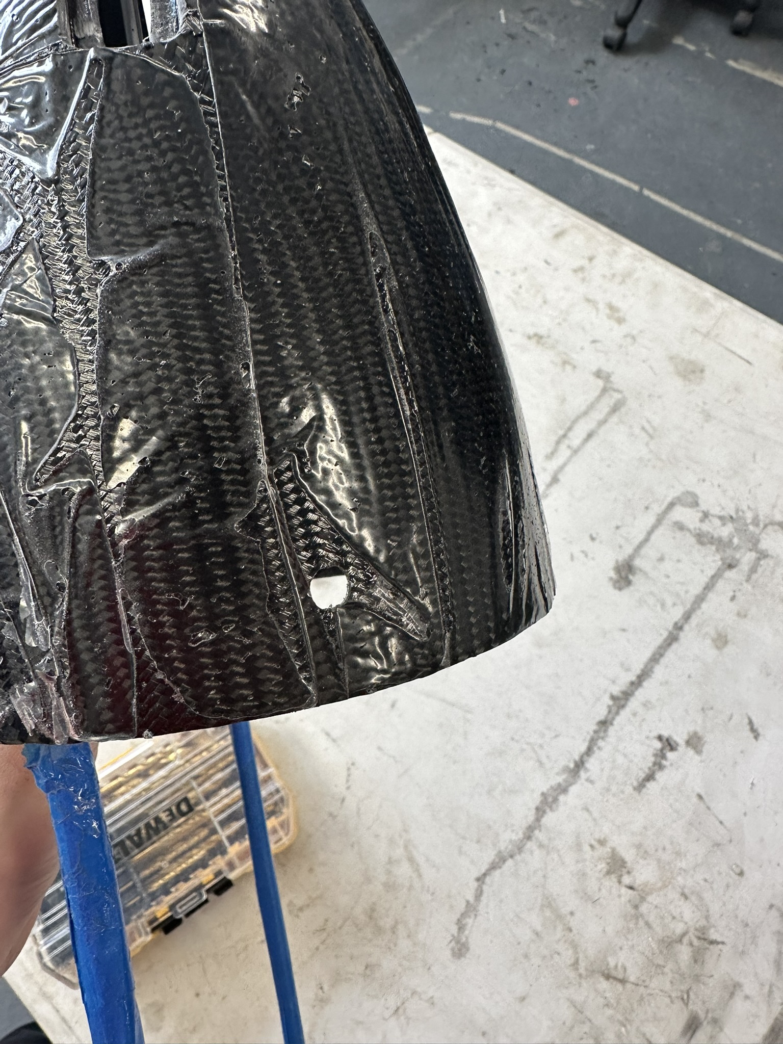
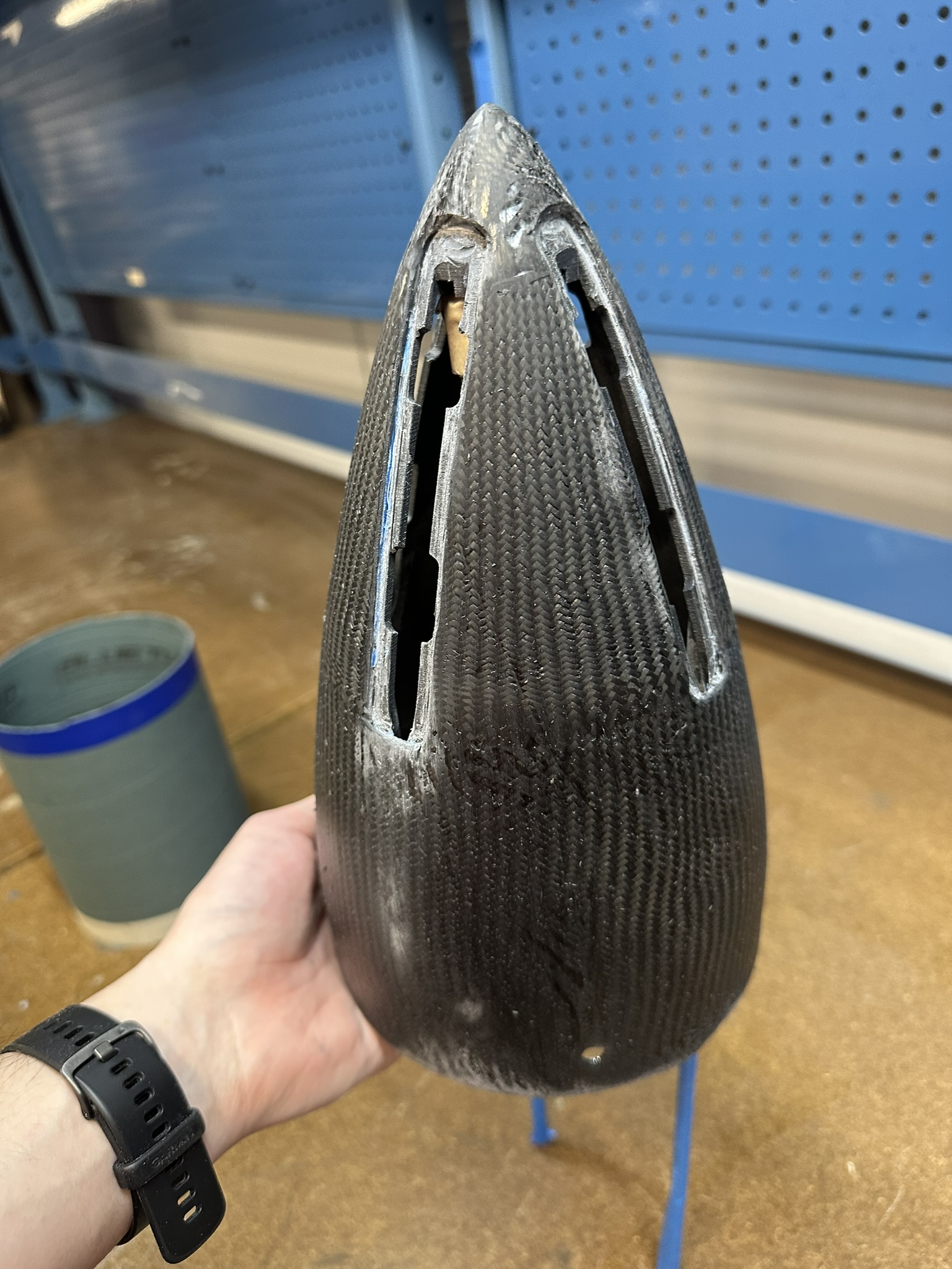
Nose cone 2 during the Dremel step and the finished nose cone 2 (right).
Landing Gear Assembly
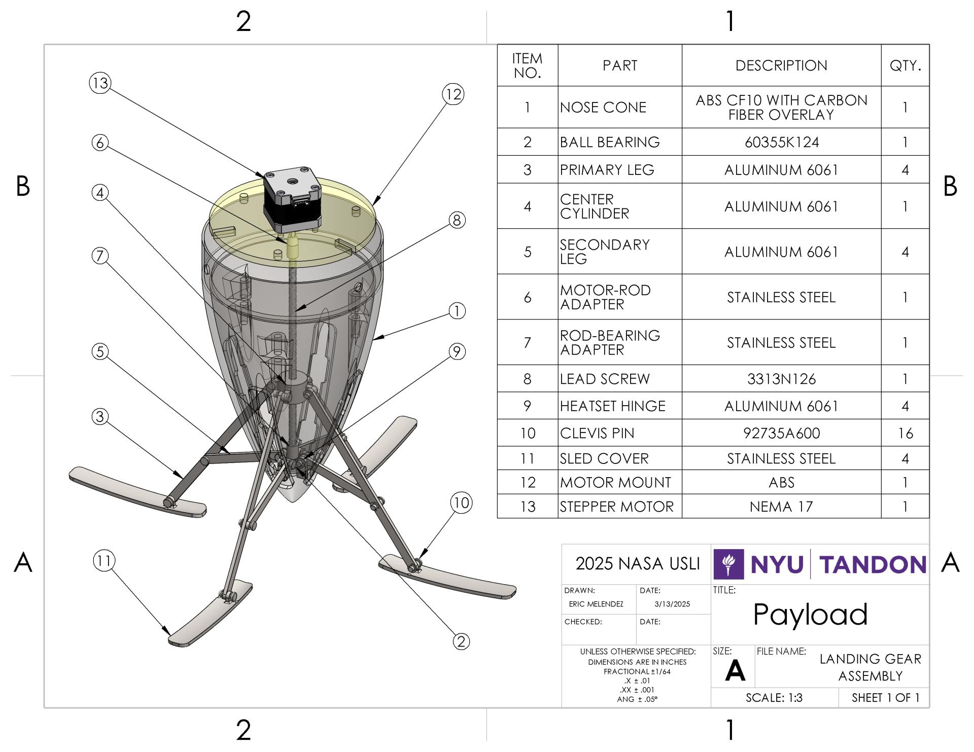
The landing gear assembly was designed with parts which would be easily manufactured. However, due to the team’s lack of experience with metal machining, the manufacturing work was done by NYU Tandon’s machinist, Oleg Shargorodskiy. I drew up the following drawings which were given to the machinist for fabrication. Working with the machinist’s suggestions, the center cylinder was modified in order to run the same CNC tool path multiple times instead of having to write separate tool paths for each side.
Because of the earlier wooden prototype, the assembly process was simple. The following images document the assembly process.
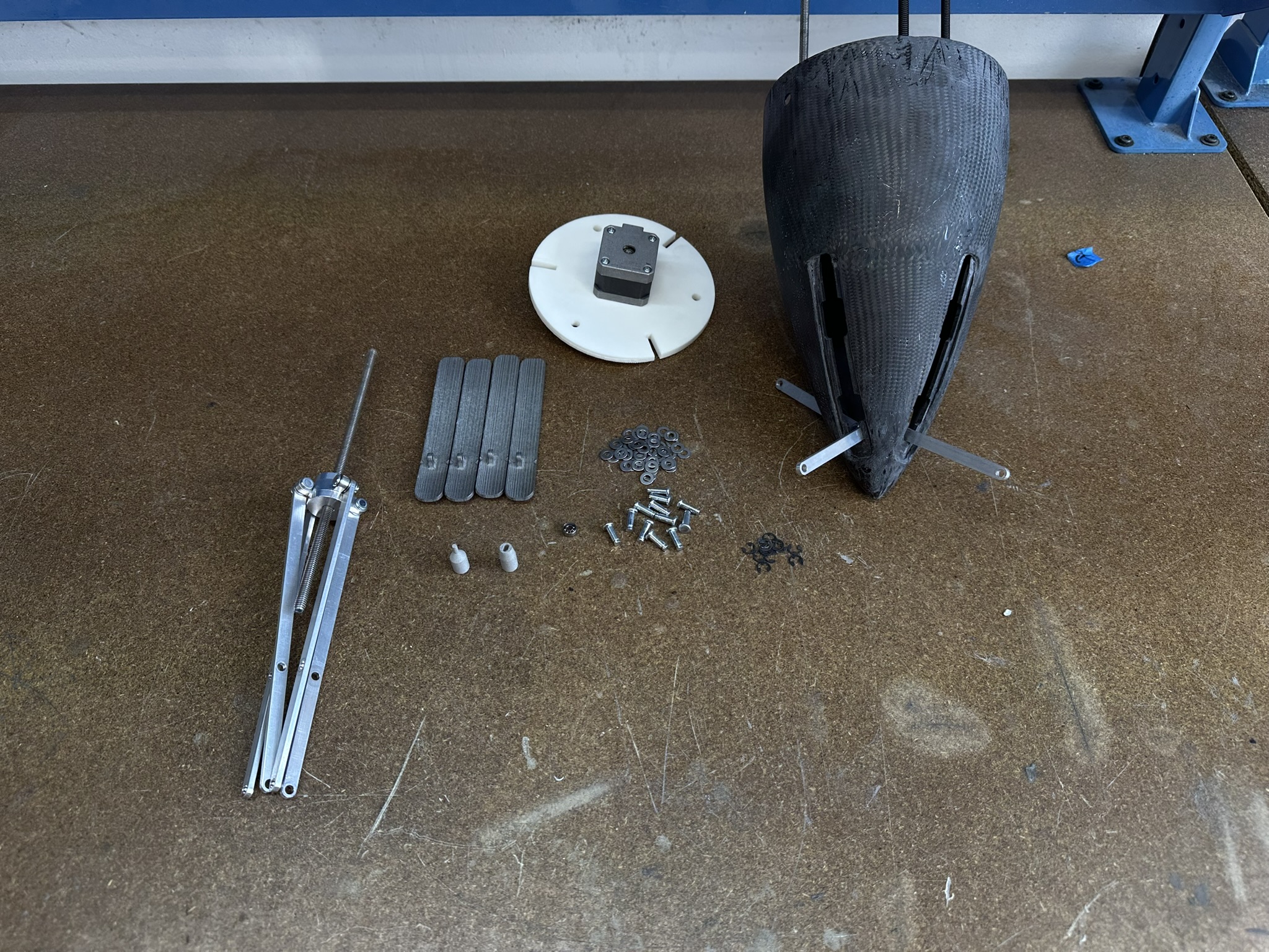
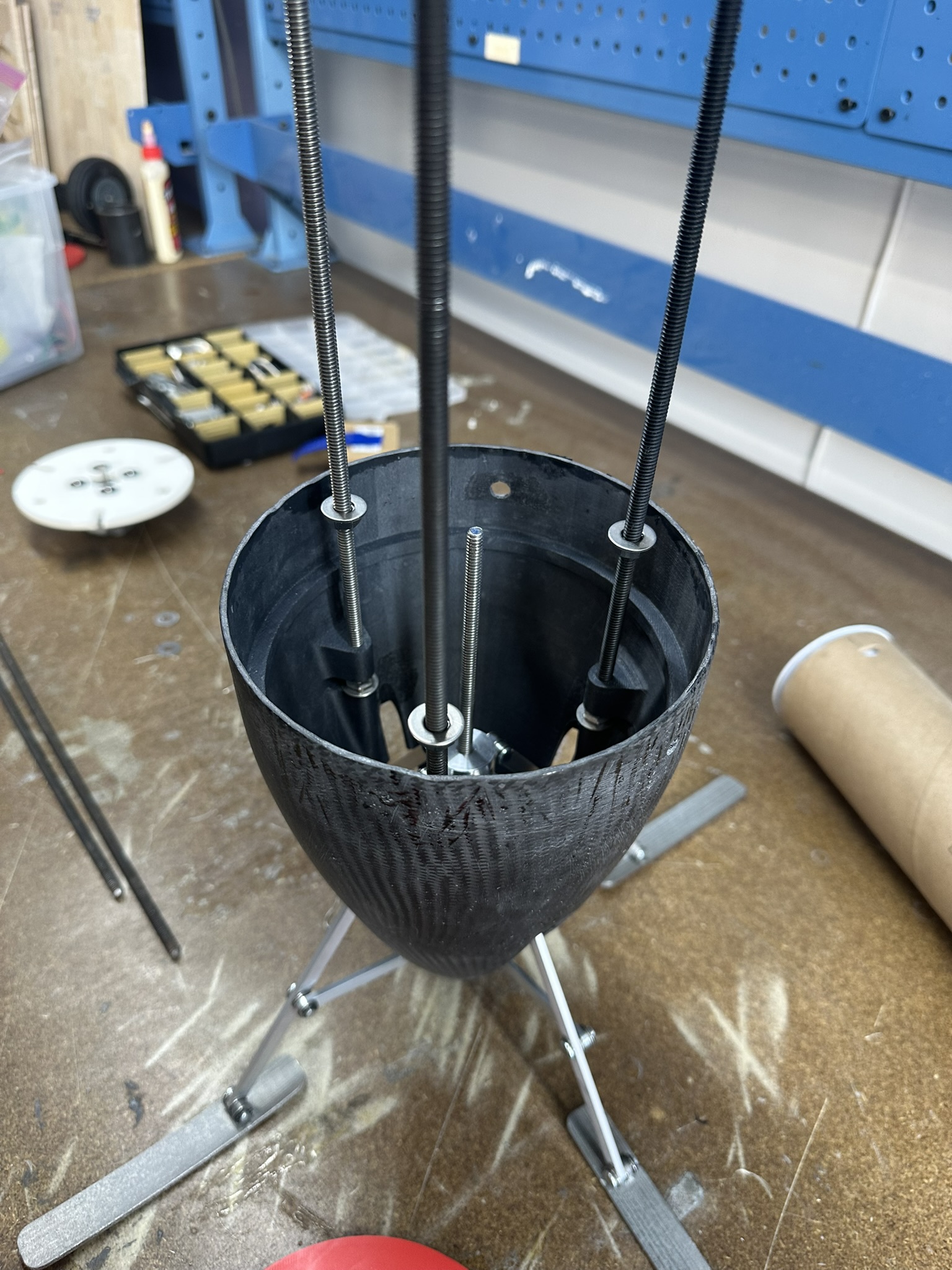
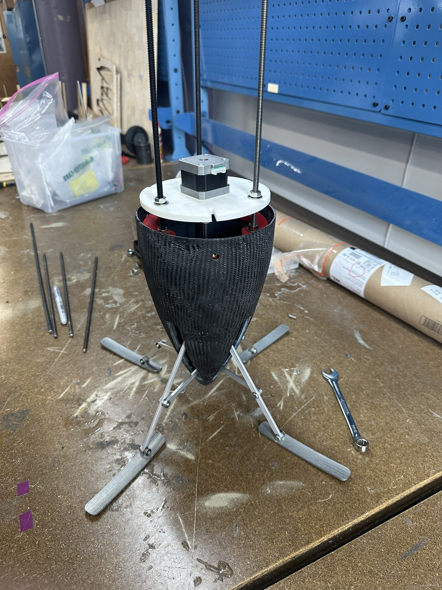
Landing gear final assembly process.
Video demonstration of fully integrated landing gear deploying. Note: the legs get a bit stuck on the first test–this issue was fixed before test 2.
Reflections & Lessons Learned
This project was my first exposure to design for manufacturing. During an initial design consolation with my sub-team leads, I quickly realized my assembly was impossible to manufacture. They turned me in the direction of McMaster-Carr and I redesigned while constantly asking myself how every part would be manufactured. With manufacturing in the back of my mind, a curiosity sparked which would send me to my local makerspace the following summer in Austin, TX where I was trained on a manual lathe and made several beginner projects.
Following the assembly of the landing gear, it was difficult to get the bay covers to sit flush with the surface of the nose cone. With some adjustment of the placement of the middle hole in the primary legs, the bay covers eventually retracted to a flush position. However if I had to redesign the gear, I would make this adjustment process simpler. Perhaps a spring incorporated into the primary leg or a way to quickly slide the joint position where the primary and secondary leg met. All in all, the design worked but was difficult to adjust.
Results
The launch vehicle holding the final landing gear assembly suffered a Catastrophic Accident on Take Off (CATO) which prevented the flight test of the fully integrated landing gear system. This CATO also prevented the team’s final launch in Huntsville, Alabama. Despite the inability to launch the vehicle, myself and two other members decided to attend the conference in Alabama to both show our own engineering work and check out the engineering work of the other teams.
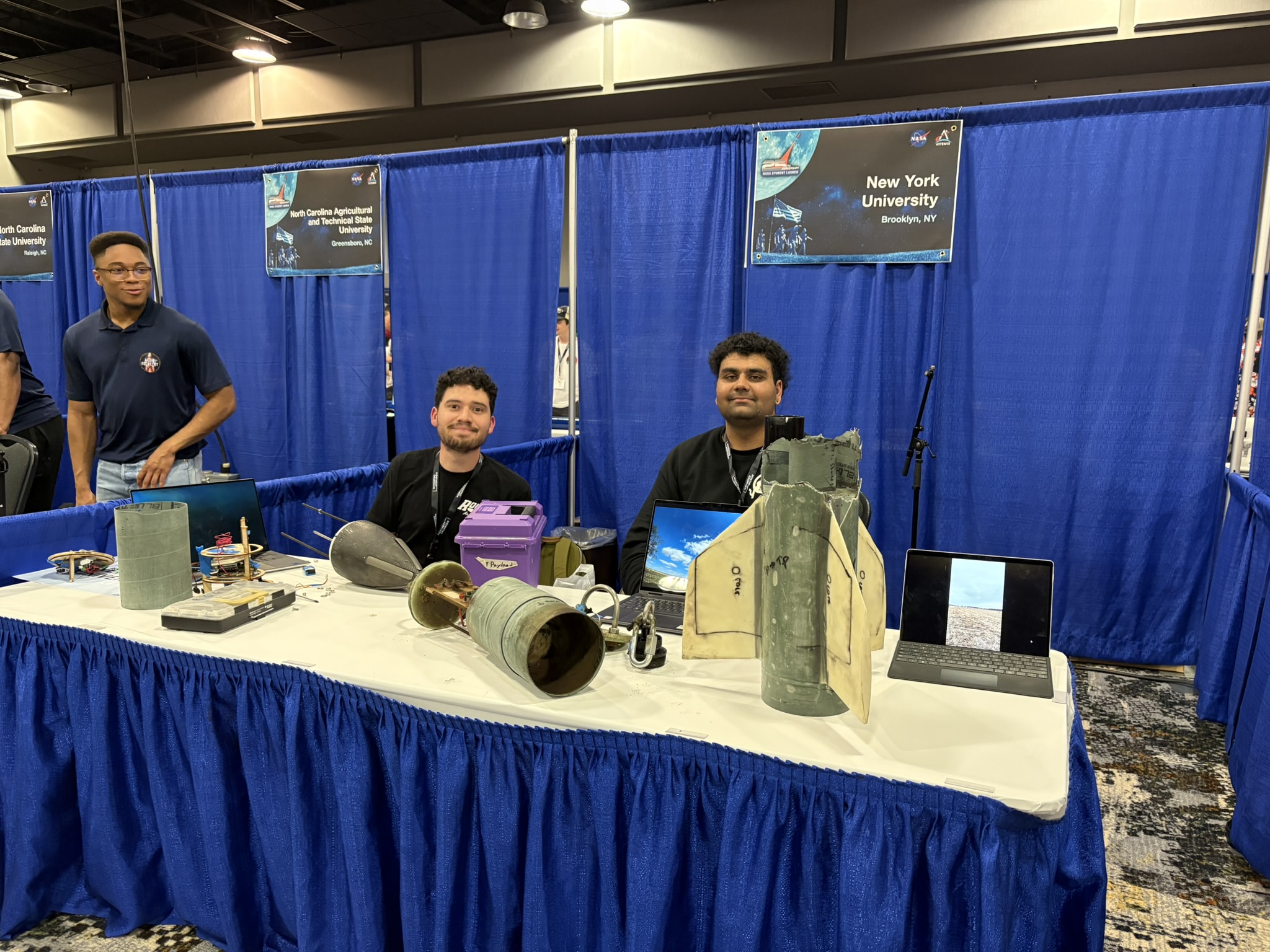
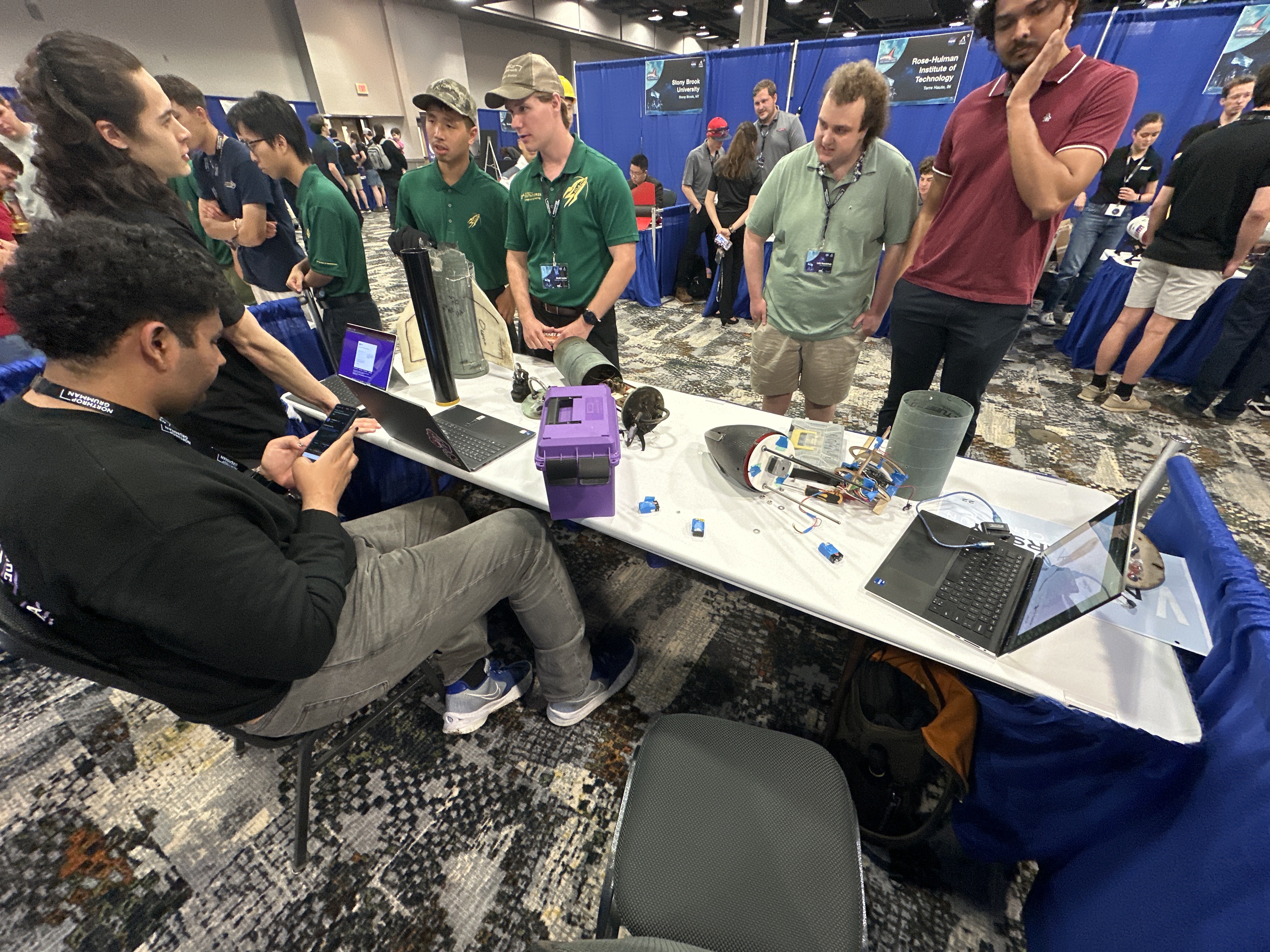
NYU Rogue Aerospace’s booth at NASA USLI conference 2025.